Hydrodynamic devices use convection to enhance the rate of mass transport to the electrode and can offer advantages over techniques which operate in stagnant solution. The addition of convection to the cell usually results in increased current and sensitivity in comparison to voltammetric measurements performed in stagnant solution. Also the introduction of convection (usually in a manner that is predictable) helps to remove the small random contribution from natural convection which can complicate measurements performed in stagnant solution. Finally, it is possible to vary the rate of reaction at the electrode surface by altering the convection rate in the solution and this can be usefully exploited in mechanistic analysis and electroanalytical applications. In the discussion below a range of traditional and recent developments in the field of hydrodynamic techniques and their potential applications are outlined.
Hydrodynamics
There are two main approaches of introducing convection into the electrochemical cell. First the electrode can be held in a fixed position and solution is flowed over the surface by an applied force (usually a pressure). Second the electrode can be designed to move which acts to mix the solution via convection. The introduced (forced) convection is generally made to be considerably stronger than any natural convection processes and therefore the influence of natural convection becomes insignificant on the electrolysis reaction. To allow quantitative analysis it is vital that the forced convection introduced to the cell is predictable. The cell and experimental conditions are therefore designed so that the solution flow within the cell becomes laminar. You will recall from the mass transport section (link) that in this case solution flows in a well defined and non mixing way. The the two figures below show the extremes of flow behaviour through a pipe. First turbulent conditions where the flow is essentially random and unpredictable and second the well defined Laminar flow conditions.
The transition between laminar and turbulent flow can be predicted using the concept of the Reynolds number. When laminar flow prevails the fluid dynamics within the cell can be predicted by the Navier-Stokes equations and these allow the calculation of the velocity throughout the device. Once these have been predicted the concentration of the reagents and the relationship between the current and the transport rate within the cell can then be calculated.
Hydrodynamic techniques
In this section we take a historical look at the development of hydrodynamic devices and the voltammetric behaviour of the different techniques. The following techniques are covered:
-
The Dropping Mercury Electrode
-
The Rotating Disc and Ring Disc Electrode
-
The Wall Jet Electrode
-
The Channel Electrode
-
The Confluence Reactor
The Dropping Mercury Electrode
The first of the hydrodynamic techniques developed was the Dropping Mercury Electrode (DME). In this arrangement a fine capillary is connected to a reservoir of mercury. The cell is designed so that mercury is allowed to flow down the capillary at a controlled rate and out into the solution.
Electrical contact to the mercury is made in the reservoir and a reference and counter electrode are sited in the electrolyte solution. Voltammetry can performed in an identical manner to that described earlier, however, now the electrode is constantly changing area and so a linear sweep voltammogram will exhibit significantly different behaviour. The current can be seen to go through a series of peaks and troughs as the voltage is swept. As the mercury drop grows the surface area accessible to the electrolyte also increases and consequently the current increases. However, at some point the Mercury drops from the tip leaving a small new area in contact with the electrolyte, consequently the current drops rapidly at this point before gradually increasing as the drop grows again. This behaviour is repeated throughout the scan. Clearly this process is not something that is easily predicted and the fluid dynamics are still not fully understood for this particular device. However, this technique proved very popular due to the ability to continually refresh the electrode surface during the experiment.
The Rotating Disc and Ring Disc Electrode
Due to the limitations of the DME a new device was developed called the Rotating Disc Electrode (RDE). In this arrangement solution is brought to the surface by a Teflon disc which rotates in solution. A schematic of the cell including the working electrode is shown below. The working electrode (typically Platinum or Gold) is embedded in the top face of the Teflon shield.
When operated at rotation speeds of around 60 Hz (cycles per second) the flow profile to the electrode is laminar and so can be predicted mathematically. The figure below shows the type of flow profile that is developed when a circular object is rotated in solution and how this brings fresh reactant to the surface
The act of rotation drags material to the electrode surface where it can react. Providing the rotation speed is kept within the limits that laminar flow is maintained then the mass transport equation is given by
where the x dimension is the distance normal to the electrode surface. It is apparent that the mass transport equation is now dominated by both diffusion and convection and both these terms effect the concentration of reagent close to the electrode surface. Therefore to predict the current for this type of electrode we must solve this subject to the reactions occurring at the electrode.
A typical voltammetric measurement used with the rotating disc and other hydrodynamic systems detailed below is linear sweep voltammetry. The figure below shows a set of current voltage curves recorded for a reversible on electron transfer reaction and different rotation speeds. The scan rate used was 1 mV s-1 (compared to perhaps 20 mV s-1 for conventional cyclic voltammetry) and as can be seen the total current flowing depends upon the rotation speed used
This can be understood by returning to the concept of the 'diffusion layer' thickness controlling the flux of material to the surface. As the rotation speed is increased the distance that material can diffuse from the surface before being removed by convection is decreased. This results in a higher flux of material to the surface at higher rotation speeds. The mass transport limited current arises from the fact that the system reaches a steady state and so the current reaches a plateau once the equilibrium at the surface is driven to the products side.
We can analyse the variation of the mass transport limited current as a function of the rotation speed. This was first solved mathematically by Levich who showed the following relationship between the current and the rotation speed, for a reversible electron transfer reaction.
![]()
Therefore by plotting iL vs the square root of the rotation speed (ω) for a set of experimental data a straight will be observed if the reaction is reversible. Plots such as that shown below can be employed to analyse whether reactions involve adsorption/desorption steps chemical reactions or slow electron transfer steps.
Hydrodynamic systems lend themselves particularly to the investigation of mechanistic processes. This is because a steady supply of reactant is fed to the electrode and the ability to vary the mass transport rate provide information regarding the process under investigation. Let us use the ECE reaction as an example. In this case it is easier to reduce the product (C) from the chemical reaction that the starting material (A). A typical voltammogram for such reaction is shown below.
The current recorded in the experiment is shown as the solid line. The current that would be recorded without chemical reaction is shown as a dashed line on the figure. Analysis of this type of process is usually performed using the following ratio

Neff can vary between 1 and 2. When no chemical reaction occurs the total current flowing is the same as that for the (A) to (B) step so Neff is 1. When all of the product from the reduction of (A) is converted to (C) then Neff becomes 2 since (C) is then reduced at the electrode as well. The figure below shows how the quantity Neff varies as a function of rotation speed.
As can be seen Neff drops as the rotation speed increases. This occurs because as the rotation speed increases the product (B) from electrolysis is removed from the electrode more rapidly and therefore has less chance to react to form (C). Consequently it is possible to outrun the reaction kinetics by increasing the convection rate. Analysis of the shape of the curve in the figure can reveal the rate constant for the chemical reaction.
The Wall Jet Electrode
The Wall Jet Electrode (WJE) is an interesting alternative to the RDE. The velocity profiles were first examined (under laminar flow conditions) by Glauert who was working on the effects of jets directed towards a flat plane (for applications in vertical take off aircraft!). A fine nozel is sited within a large container of electrolyte and positioned directly above a disc working electrode. Solution is pumped through the nozel (under laminar flow conditions) and impinges on the surface containing the electrode. The reagent then flows from the surface creating a complex but predictable flow pattern. Like the rotating disc it is possible to obtain an expression for the transport of material to the electrode WJE and this can then be used to predict how the mass transport limited current would vary as a function of the solution flow rate. The WJE has found many applications in the area of Electroanalytical Chemistry.
The Channel Electrode
Like the WJE above in this device the electrode is maintained in a specific position and solution pumped through the cell. In the channel electrode (ChE) the electrode is embedded into one wall of a rectangular duct and solution pumped over the surface.
In this cell it is the volume flow rate (Vf) that controls the convection to the surface and the corresponding Levich equation for a reversible electron transfer is predicted by
![]()
h,d,w,and xe are constants for the cell size and Vf is the volume flow rate. It is possible to obtain such an expression because when the solution flow rate is controlled appropriately it is possible for a parabolic laminar profile to develop This is mathematically well defined and consequently allows quantitative analysis.
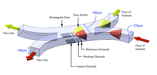
The Confluence Reactor
The above devices have allowed a range of (electro)chemical process to be examined, however, they each have limitations when reactions of interest involve bringing together different starting materials which are highly reactive. Consequently more recently new devices have been developed which permit the introduction of two or more species into a cell at a predetermined point and under well defined transport conditions. The confluence reactor (CR) shown below is constructed of two separate rectangular ducts which are independently supplied with different reagents. At some point the separation between the two ducts finishes and the separate streams can then mix. The cell is designed so that laminar flow conditions prevail and so the concentration of reagents can be computed. A detector electrode is sited in one wall and is used to sense the products as they are generated.