Introduction
In the DC analysis of resistor circuits we examined how to calculate the total circuit resistance of series components. In this section we will use this approach to analyse circuits containing series resistors and capacitors. To do this we use the capacitative reactance as the effective 'resistance' of the capacitor and then proceed in a similar manner to before.
Analysing Series RC Circuits
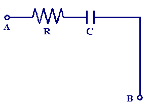
You will recall that a series circuit provides only one route for the current to flow between two points in a circuit, so for example the diagram below shows a resistor in series with a capacitor between the points A and B.

The total impedance (resistance) of this circuit is the contribution from both the capacitor and resistor. From the previous section we have seen that the capacitative reactance Xc is shifted by - 90° from the perturbing voltage signal and therefore is expressed in complex form as
| Xc = -j Xc |
The total circuit impedance is therefore
| Z = R - j Xc |
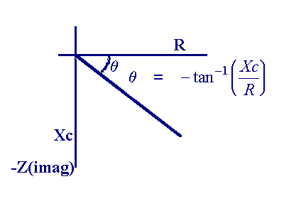
In ac analysis both the resistor and capacitor are treated as phasor quantities, so Xc is - 90° out of phase with respect to the resistor. Since Z is a phasor sum the result is presented on a phasor diagram (or complex plane)

The magnitude of the impedance - the length of vector can be calculated using
![]()
For example if we take the above circuit with a resistor of 100 Ω and Capacitor of 1x10⁻⁶ F and apply a sinusoidal voltage at a frequency of 10 Hz, the capacitative reactance can be calculated as:
| Xc = 1/(2 x 3.1415 x 10 x 1x10-6) = 15.9x10³ Ω |
and so the total impedance in rectangular form is
| Z = R - j Xc = 100 - j 15.9x10³ |
We can convert this to polar form using the method above which gives a magnitude of 15.89x10³ Ω and angle of -89.6°. The magnitude is clearly dominated by the capacitors reactance since we have considered a low operating frequency. As the frequency is altered the following response is observed (in phasor and bode forms)

The analysis of more complex series circuits is carried out by summing the individual resistances and capacitative reactances into single equivalent components and then performing the same analysis as above

