Introduction
In the previous part we identified how the resistance of a circuit can be calculated when one or more resistors are combined in series. In this section we develop our knowledge of circuit analysis by examining parallel combination of resistors.
Identifying and Analysing Parallel Circuits
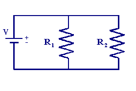
When two or more resistors are connected between identical points in a circuit the resistors are said to be in parallel. In this situation the current has a number of different possible pathways, for example in the circuit below which represents two resistors in parallel there are two possible pathways for the current to flow. 
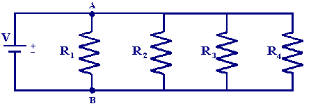
Each parallel current path is called a branch and if additional branches are added then more possible current paths are created eg

In this circuit all the connecting points along the bottom rail are equivalent to (B) and all the connecting points along the top rail equivalent to point (A). The total current flowing (iT) can be calculated by using Kirchhoff's current law.
| This states that the sum of the currents into a junction is equal to the sum of the currents out of the junction. |
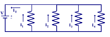
Using the example below

the total current flowing is given by
| iT = i1 + i2 + i3+ i4 |
The voltage dropped across each branch is identical to the source voltage (V), so using Ohms law to replace each current with the voltage and resistance gives
| V/RT = V/R1 + V/R2 + V/R3 + V/R4 |
Cancelling the voltage terms shows how the total resistance can be calculated from the individual components ie
| 1/RT = 1/R1 + 1/R2 + 1/R3 + 1/R4 |
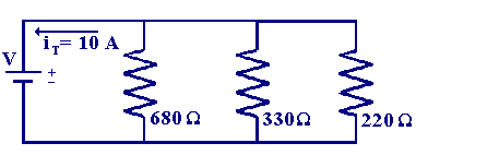
Now let us use an example to evaluate the individual currents flowing in each branch of the following circuit.

As we know the total current flowing in the circuit we can work out the value of the voltage source by calculating the total resistance and then using Ohms law to convert this to the applied voltage.
| RT = 1/(1/R1 + 1/R2 + 1/R3) = 1/(1/680 + 1/330 + 1/220) = 111 Ω |
and so the source voltage (V) is
| V = iTRT = 10 x 111 = 1110 V |
As we know that each branch has the source voltage dropped across it we are now able to evaluate the current for each branch
| i1 = 1110/680 = 1.63 A |
| i2 = 1110/330 = 3.36 A |
| i3 = 1110/220 = 5.05 A |
We have now seen how to analyse circuits containing resistors in series or parallel, in many electrochemical measurements we find that the systems can be quantified in terms of combinations of series and parallel components. The circuit analysis approach for these types of problems are set out in the following section

