Introduction
In the previous part we identified the resistor as one possible component of an electrical circuit. In this section we look at how resistors can be combined in series within a circuit, this is relevant to the analysis of current flow through electrolyte solution as the medium can be considered as have a specific resitivity.
Identifying and Analysing Series Circuits
A series circuit provides only one route for the current to flow between two points in a circuit, consequently the current flowing through each individual resistor is the same. The diagram below shows three resistors in series between the points A and B.

When resistors are connected in series the total circuit resistance RT can be calculated by summing the individual resistances i.e.
|
RT = R1 + R2 + R3 |
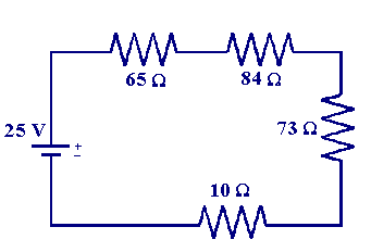
Using this information we can calculate the total resistance of the circuit below, along with the current flowing and the potential dropped across each individual resistor

the total resistance is
| RT = 65 + 84 + 73 + 10 = 232 Ω |
to evaluate the current flowing we use Ohm's law which tells us we must divide the applied voltage (25 V) by the total circuit resistance
| i = V/ RT = 25/232 = 107.76 mA (0.10776 A) |
Having calculated the current flowing it is now possible to work out the potential dropped over each resistor. We again use Ohm's law, recalling that for a series circuit the current through each resistor is the same, so for the 65 Ω resistor the voltage dropped is
| 0.10776 x 65 = 7.004 V |
similarly for the other resistors we get
| 0.10776 x 84 = 9.051 V |
| 0.10776 x 73 = 7.867 V |
| 0.10776 x 10 = 1.078 V |
This result leads to another concept first noted by Kirchhoff for series circuits or loops. By summing the voltage drops over each resistor we end up with the source voltage. Kirchhoff stated this result as follows: the sum of all the voltages around a single closed loop in a circuit is equal to the total source voltage in that loop We have now introduced the main concepts required to examine the current, resistance and voltage properties of circuits which contain resistors in series. In the next section we will examine the analogous behaviour of parallel circuits.

