Introduction
In this section we look at how to analyse circuits which contain resistors in series and parallel combinations.
Identifying and Analysing Parallel Circuits
The figure below shows a basic circuit which contains a series-parallel combination of resistors. The resistance from point A to point B is R1, the resistance from B to C is the combination of R2 and R3 in parallel. The total circuit resistance (from point A to C) is the series resistor R1 in combination with the parallel components.
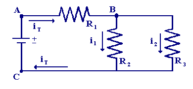
A more complex example of a series-parallel resistor circuit is shown below
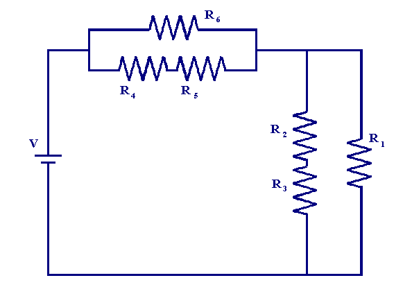
here the resistor R6 is in parallel with the resistors R4 and R5. Also the resistors R3, R2 and R1 form a parallel combination. It is also clear that the two parallel combinations are in series with one another. To calculate the total resistance of a series-parallel circuit we use the techniques we have developed in the two previous sections. To illustrate the basic analysis procedures we will use a couple of examples. First we consider the circuit below
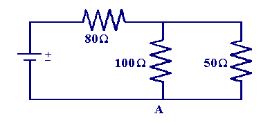
and wish to calculate the total circuit resistance. The current will clearly pass through the 80 Ω resistor before splitting into two components in the parallel combination, at point A the parallel branch currents will recombine and flow to the positive terminal. To calculate the total circuit resistance first we work out the effective resistance of the parallel combination, using the method from the previous section.
| Rparallel = 1/(1/100 + 1/50) = 33.3 Ω |
Using this result we can redraw the circuit above as follows
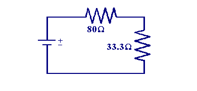
The total circuit resistance can now be calculated by summing the two series resistances.
| RT = 80 + 33.3 = 113.3 Ω |
Next we will examine the slightly more complex circuit below.
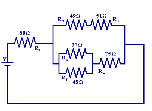
Using the same procedure as above we first work out the equivalent resistance of each of the parallel combinations to get the effective resistance in series with R1. We begin with the resistors R4 and R5
| R5-4 = 1/(1/37 + 1/45) = 20.3 Ω |
Now we work out the resistance in each of the parallel branches. For the top branch the resistance is equal to the sum of the resistors R2 andR3
| R3-2 = 49 + 51 = 100 Ω |
for the bottom branch it is equal to the sum of the resistors R6 andR5-4
| R6-5-4 = 75 + 20.3 = 95.3 Ω |
Now we are left with a circuit equivalent to the figure below
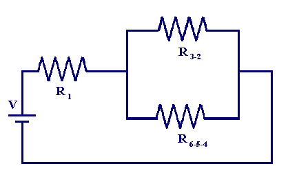
So all that is left is to work out the effective resistance of the parallel combination R6-5-4 and R3-2
| R6-5-4-3-2 = 1/(1/100 + 1/95.3) = 48.8 Ω |
So the total circuit resistance is
| RT = 80 + 48.8 = 128.8 Ω |
The systematic approach we have introduced above can be used to work out the effective resistance of any specific circuit. However if we know the voltage or current properties of the circuit we can employ the same approach to calculate the unknowns. In the AC circuit analysis section which follows we will look at circuits which contain resistors, capacitors and inductors and use a very similar strategy to analyse the circuit response of these systems.

