The application of microfabrication technologies in the field of (electro)chemical microreactor design has led to an explosion of new potential (electro)analytical devices. In this section we briefly examine the development of microelectrochemical reactors which exploit hydrodynamic conditions to create new devices for the investigation of electrolysis reactions and analytical sensing.
Construction of Microelectrochemical Reactors
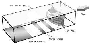
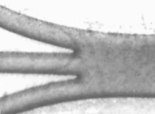
Photolithographic and soft lithographic techniques are used to produce channels which are typically about 10 - 100 μm in depth, with a channel width in the range 10-500 μm. A schematic of a typical single channel microelectrochemical reactor is depicted below. Images of microfabricated channels and electrodes are also shown below.
 |
 |
Hydrodynamic Voltammetry in Microelectrochemical Reactors
Once complete electroactive reagent solution is pumped through the cell and voltammetric measurements performed in an analogous manner to those discussed in the hydrodynamic voltammetry section. The figure below reveals two hydrodynamic voltammograms recorded at different volume flow rates within a microelectrochemical reactor for a reagent solution containing a electroactive material undergoing a transport limited one electron oxidation at the working electrode.
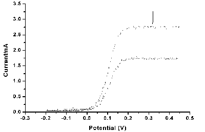
The response observed is similar to that seen in the larger scale channel electrode described earlier. Indeed the variation of the transport limited current as a function of the velocity of solution through the cell also shows the cube root relationship observed for macroscopic channel cells. However, it should be noted that the full analysis of the current variation does require more complex 3 dimension mass transport modelling due to the fluid flow properties within the cells. At this stage these devices have yet to be fully exploited for mechanistic analysis, however, the reactors should offer some significant benefits over the traditional techniques such as the rotating disc electrode etc. These benefits should include access to more rapid chemical and electrochemically reactive processes (due to the higher rates of mass transport within the cells) and as a result of the microfabrication approach a vast range of potential cell designs will be available offering the opportunity to 'tailor' make specific configurations for a particular chemical investigation.
Multiphase Microelectrochemical Reactors
The application of microreactor technology has not been restricted to the analysis of processess occurring in single solvent phases. Recently electrochmeical devices have been developed to permit the analysis of reactions occurring between reagents flowing in immiscible liquids. The figure below shows a schematic of a typical reactor designed for two phase flow measurements
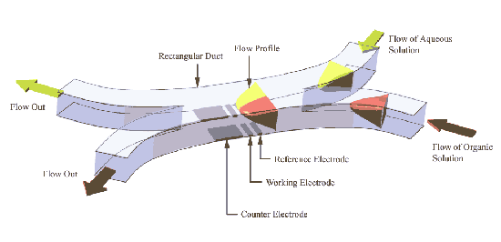
In this case a two inlet arrangement is employed with the immisicible solvent streams (eg water/dichloroethane) introduced into the device via separate inlets. At some predetermined point the two streams converge and reagents may then transfer between the two phases (eg phase transfer catalysis). Electrode sensors are placed within the separate streams to permit analysis of the reagents in each solvent and to detect the products of any reactions occurring. In the figures below an image recorded of a multiphase flow measurement is shown for a 'U tube' environment, (a blue dye has been added to the organic phase to aid visualisation) and on the right a straight cell constructed with mircroelectrode sensors in each stream.
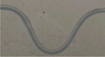 |
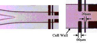 |
This microreactor approach also permits more complex multiphase flow conditions to be examined. For example in the images below the approach has been extended to a three phase environment, where in this case three solvent streams containing different chemical reagents may be brought together at a predetermined point to permit chemical reaction. The figure on the left below shows the three inlet arrangement and on the right an image taken about 2.5 cms from the inlet region. It is apparent that a chemical reaction has occurred in this case an interfacial electron transfer has created the coloured product in the central stream.
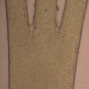 |
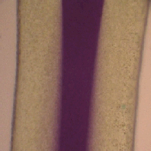 |

