Lead researcher: Dr Bart Hallmark
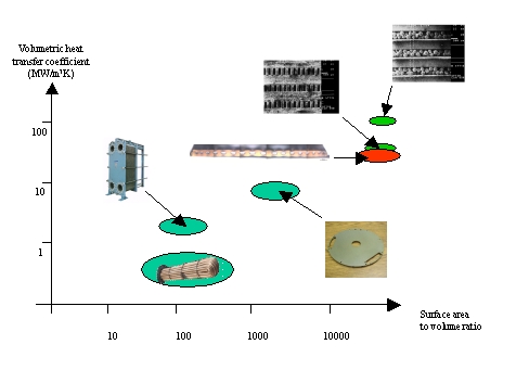
Early preliminary studies showed that, despite their plastic construction, poly- (ethylene) MCFs possessed attractive heat transfer properties. These properties, coupled with the flexibility and the low-cost nature of the MCF material has led to some potentially very interesting heat exchange areas being investigated. Previous studies into micro heat exchange using copper based systems revealed performance in terms of volumetric heat transfer coefficient between 40 MW/m3K and 80 MW/m3K. MCF systems, when both sides of the film are used for heat transfer, yields volumetric heat transfer coefficients up to 35 MW/m3K and between 15 MW/m3K and 20 MW/m3K when a single side of the film is used. This is despite poly- (ethylene) having a thermal conductivity around one thousand times lower than copper. The schematic plot below compares the performance between different types of heat exchanger; the red indicates MCF. As the plot shows, the key behind the thermal performance of MCF heat exchangers is the large surface area to volume ratio.
 |
Heat transfer in electrical systems
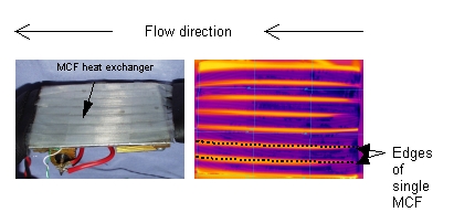
The small size and flexibility of MCFs could be advantageous in systems where large amounts of heat get dissipated in over small, difficult to access, surfaces. With this in mind, heat exchange was studied using MCFs to extract heat from an aluminium plate heated by an electrical load. Ice cold water was pumped through a heat exchanger that consisted of seven low-voidage MCFs in parallel; thermal imaging was used to assess the detailed operation of the exchanger. This is shown in the photograph below.
 |
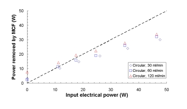
Heat extraction as a function of flow-rate and applied electrical load was calculated - the results are plotted in the graph below. This plot shows that, despite only one side of the MCF being used for heat exchange and despite the electrical load dissipating some heat via natural convection, the majority of the power dissipated was taken away in the fluid flow within the MCF heat exchanger. In this plot, the dotted line signifies y=x, or where the electrical load applied is equal to the thermal load removed.
 |
Return to MCF applications page

